RDL25A
1.Machine Purpose:
The machine is mainly used to process the connecting holes of the base rail and at rail waist in turnout rail. The drilling process of cemented carbide drill is adopted, which can realize semi-automatic production, reduce the labor intensity of workers, and greatly improve the labor productivity.
2.Machine Features:
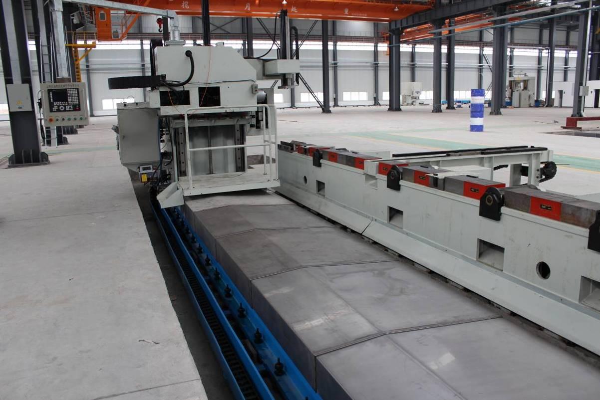
i.The bed of the machine tool is separated from the worktable, and the guide rail pair of the bed is arranged horizontally to increase the service life of the guide rail pair; the welded steel plate structure is adopted, and the accuracy and stability are ensured by annealing, stress relief and artificial aging treatment.
ii.A powerful electromagnetic chuck is installed on the worktable of the machine tool to tighten the workpiece. Pay attention to the order from the middle to both sides when the electromagnetic sucker is closed, and pay attention to the sealing and waterproof.
iii.The mobile column adopts steel plate welding structure, which is annealed to remove stress and artificial aging treatment to ensure accuracy stability. The moving column is laid on the bed by the slide blocks on the two horizontal ultra-high bearing capacity linear rolling guide pairs installed on the bed.
iv.The z-axis slide plate and RAM are made of casting (HT250), which ensures the good shock absorption and stability of the machine tool. The output shaft of the spindle motor is equipped with a synchronous pulley, which is transmitted to the BT50 precision spindle produced by Taiwan Kenturn company through the synchronous belt. It has high tensile strength, long service life and low noise and vibration when running at high speed.
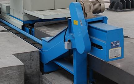
v.Chain plate automatic chip remover is flat chain type, and is installed in the middle of the bed work table. The scrap iron falls on the chip conveyor through the inclined plate on the worktable, and the scrap iron is transported to the chip carrier at its head through the chip conveyor.
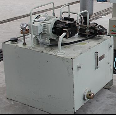
vi.The equipment is equipped with two hydraulic stations, one is installed on the mobile column, which is mainly used for balancing cylinder, pressing cylinder and knife cylinder; the other is installed on the foundation, which is mainly used for lifting cylinder and pulling cylinder of lifting conveying roller table. All hydraulic stations use variable vane pump to provide pressure oil, which meets the requirements of energy saving and environmental protection.
vii.There are three CNC axes in the machine tool, each of which is guided by precision linear rolling guide pair. Except that the x-axis is driven by AC servo motor connected with imported high-precision clearance elimination helical gear and rack pair through low backlash worm gear reducer, the other CNC axes are driven by AC servo motor through precision ball screw pair.
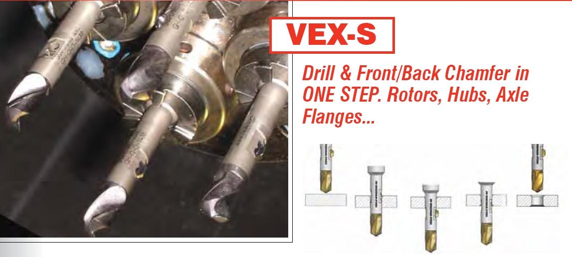
viii.The drilling tool adopts index able cemented carbide u drill, and the spindle is cooled by air mist.
ix.Siemens 828d CNC system is used in the CNC system, which can monitor the drilling process in real time.
3.Main Technical Specifications:
Specification of processed rail | Type of stock rail | 43Kg/m、50Kg/m、60Kg/m、75Kg/m、UIC54、UIC60 |
At rail model | 50AT、60 AT、UIC60D40 | |
Special section wing rail | 60TY | |
Rail size range | Bottom width | 114-152mm |
Rail height | 128-192mm | |
Abdominal thickness | 14.5-44mm | |
Rail length (after sawing) | 6-25m | |
texture of material | U71Mn σb≥90Kg/mm² HB250 PD3 σb≥98Kg/mm² HB290-310 | |
Drilling bit | Diameter | φ20~φ33 |
Length range | 3D~4D | |
Processing requirements | Range of hole height | 35~100mm |
Number of holes on each rail | 1~4 | |
Allowable deviation of adjacent hole spacing | ±0.3mm | |
Allowable deviation between rail end face and nearest hole distance | ±0.5mm | |
Allowable deviation of farthest hole distance of rail | ±0.5mm | |
Allowable deviation of aperture size | 0~+0.3mm | |
Hole wall roughness | Ra12.5 | |
Allowable deviation of hole center height (from rail bottom) | ±0.3mm | |
Mobile column (including drill pin power box) | Quantity | 1 set |
Spindle taper hole | BT50 | |
Spindle speed range (stepless speed regulation) | 10~3200r/min | |
Spindle servo motor power | 37kW | |
Vertical slide stroke (Y-axis) | 800mm | |
Servo motor power of vertical sliding table (Y-axis) | 3.1kW | |
Horizontal drilling feed stroke (Z-axis) | 350mm | |
Horizontal drilling feed (Z-axis) servo motor power | 3.1kW | |
Horizontal travel of column (x-axis) | 25m | |
Column horizontal movement (x-axis) servo motor power | 3.1kW | |
Maximum moving speed of x-axis | 10m/min | |
Y. Maximum moving speed of z-axis | 8m/min | |
Electric permanent magnet sucker | Quantity | 1 set |
Sucker size (L × w × h) | 250×200×120mm | |
Working suction | ≥200N/cm² | |
Side push cylinder | Cylinder diameter × stroke | Φ50×70mm |
Single cylinder side thrust | 700Kg | |
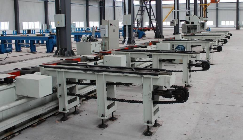
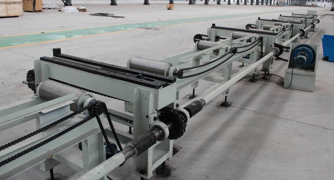
Lifting roller table | Quantity | 1 set |
Conveying speed | ≤15m/min | |
Auxiliary hold down cylinder | Quantity | 1 set |
Pressing force | ≥1500Kg/set | |
Chip removal | Chip conveyor type | Flat chain |
Chip removal speed | 2m/min | |
Chip removal motor power | 2.2kW | |
Hydraulic system | Quantity | 2 sets |
Hydraulic pump pressure / flow / power | 6-6.5Mpa/25L/min/4kW 1 set | |
Hydraulic pump pressure / flow / power | 5.5-6Mpa/66L/min/7.5kW 1 set | |
Electrical system | Numerical control system | Siemens 828d |
Number of CNC axes | 5+1 | |
Compressed air supply pressure | 0.6Mpa | |
Overall dimensions (L× W× H) | About 57m×8.7m×3.8m |
4.Work Environment:
1).Power supply: 3 phase 4 lines 380±10%V 50±1HZ
2).Compressed air pressure: ≥0.5MPa
3).Temperature: 0-40°C
4).Humidity: ≤75%
1.Machine Purpose:
The machine is mainly used to process the connecting holes of the base rail and at rail waist in turnout rail. The drilling process of cemented carbide drill is adopted, which can realize semi-automatic production, reduce the labor intensity of workers, and greatly improve the labor productivity.
2.Machine Features:
i.The bed of the machine tool is separated from the worktable, and the guide rail pair of the bed is arranged horizontally to increase the service life of the guide rail pair; the welded steel plate structure is adopted, and the accuracy and stability are ensured by annealing, stress relief and artificial aging treatment.
ii.A powerful electromagnetic chuck is installed on the worktable of the machine tool to tighten the workpiece. Pay attention to the order from the middle to both sides when the electromagnetic sucker is closed, and pay attention to the sealing and waterproof.
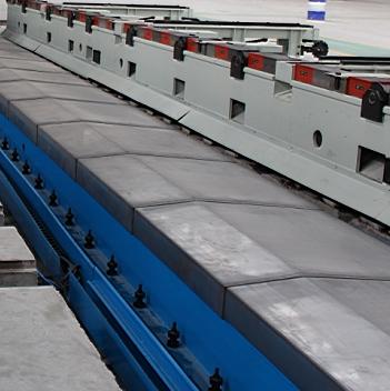
iii.The mobile column adopts steel plate welding structure, which is annealed to remove stress and artificial aging treatment to ensure accuracy stability. The moving column is laid on the bed by the slide blocks on the two horizontal ultra-high bearing capacity linear rolling guide pairs installed on the bed.
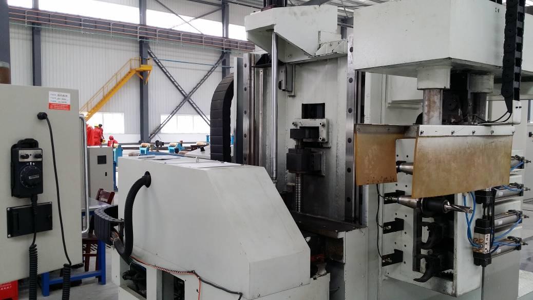
iv.The z-axis slide plate and RAM are made of casting (HT250), which ensures the good shock absorption and stability of the machine tool. The output shaft of the spindle motor is equipped with a synchronous pulley, which is transmitted to the BT50 precision spindle produced by Taiwan Kenturn company through the synchronous belt. It has high tensile strength, long service life and low noise and vibration when running at high speed.
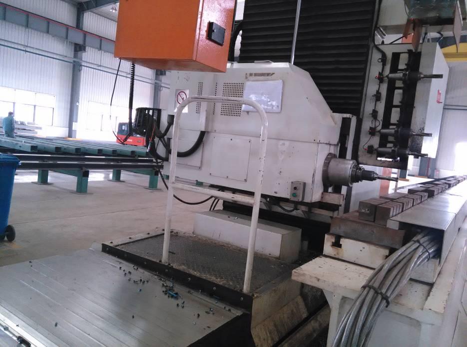
v.Chain plate automatic chip remover is flat chain type, and is installed in the middle of the bed work table. The scrap iron falls on the chip conveyor through the inclined plate on the worktable, and the scrap iron is transported to the chip carrier at its head through the chip conveyor.
vi.The equipment is equipped with two hydraulic stations, one is installed on the mobile column, which is mainly used for balancing cylinder, pressing cylinder and knife cylinder; the other is installed on the foundation, which is mainly used for lifting cylinder and pulling cylinder of lifting conveying roller table. All hydraulic stations use variable vane pump to provide pressure oil, which meets the requirements of energy saving and environmental protection.
vii.There are three CNC axes in the machine tool, each of which is guided by precision linear rolling guide pair. Except that the x-axis is driven by AC servo motor connected with imported high-precision clearance elimination helical gear and rack pair through low backlash worm gear reducer, the other CNC axes are driven by AC servo motor through precision ball screw pair.
viii.The drilling tool adopts index able cemented carbide u drill, and the spindle is cooled by air mist.
ix.Siemens 828d CNC system is used in the CNC system, which can monitor the drilling process in real time.
3.Main Technical Specifications:
Specification of processed rail | Type of stock rail | 43Kg/m、50Kg/m、60Kg/m、75Kg/m、UIC54、UIC60 |
At rail model | 50AT、60 AT、UIC60D40 | |
Special section wing rail | 60TY | |
Rail size range | Bottom width | 114-152mm |
Rail height | 128-192mm | |
Abdominal thickness | 14.5-44mm | |
Rail length (after sawing) | 6-25m | |
texture of material | U71Mn σb≥90Kg/mm² HB250 PD3 σb≥98Kg/mm² HB290-310 | |
Drilling bit | Diameter | φ20~φ33 |
Length range | 3D~4D | |
Processing requirements | Range of hole height | 35~100mm |
Number of holes on each rail | 1~4 | |
Allowable deviation of adjacent hole spacing | ±0.3mm | |
Allowable deviation between rail end face and nearest hole distance | ±0.5mm | |
Allowable deviation of farthest hole distance of rail | ±0.5mm | |
Allowable deviation of aperture size | 0~+0.3mm | |
Hole wall roughness | Ra12.5 | |
Allowable deviation of hole center height (from rail bottom) | ±0.3mm | |
Mobile column (including drill pin power box) | Quantity | 1 set |
Spindle taper hole | BT50 | |
Spindle speed range (stepless speed regulation) | 10~3200r/min | |
Spindle servo motor power | 37kW | |
Vertical slide stroke (Y-axis) | 800mm | |
Servo motor power of vertical sliding table (Y-axis) | 3.1kW | |
Horizontal drilling feed stroke (Z-axis) | 350mm | |
Horizontal drilling feed (Z-axis) servo motor power | 3.1kW | |
Horizontal travel of column (x-axis) | 25m | |
Column horizontal movement (x-axis) servo motor power | 3.1kW | |
Maximum moving speed of x-axis | 10m/min | |
Y. Maximum moving speed of z-axis | 8m/min | |
Electric permanent magnet sucker | Quantity | 1 set |
Sucker size (L × w × h) | 250×200×120mm | |
Working suction | ≥200N/cm² | |
Side push cylinder | Cylinder diameter × stroke | Φ50×70mm |
Single cylinder side thrust | 700Kg | |
Lifting roller table | Quantity | 1 set |
Conveying speed | ≤15m/min | |
Auxiliary hold down cylinder | Quantity | 1 set |
Pressing force | ≥1500Kg/set | |
Chip removal | Chip conveyor type | Flat chain |
Chip removal speed | 2m/min | |
Chip removal motor power | 2.2kW | |
Hydraulic system | Quantity | 2 sets |
Hydraulic pump pressure / flow / power | 6-6.5Mpa/25L/min/4kW 1 set | |
Hydraulic pump pressure / flow / power | 5.5-6Mpa/66L/min/7.5kW 1 set | |
Electrical system | Numerical control system | Siemens 828d |
Number of CNC axes | 5+1 | |
Compressed air supply pressure | 0.6Mpa | |
Overall dimensions (L× W× H) | About 57m×8.7m×3.8m |
4.Work Environment:
1).Power supply: 3 phase 4 lines 380±10%V 50±1HZ
2).Compressed air pressure: ≥0.5MPa
3).Temperature: 0-40°C
4).Humidity: ≤75%